


There are a few write-ups regarding on the net already, but, as most WD members start by searching on home ground, I thought it wise to do one of my own ")
Play in my rear drive became increasingly pronounced, so after my last ride to the mountains of Pedi, and I realized the bike would not start due to a broken wire in my ignition, I decided it was time for some proper TLC.
On the agenda:
1) Renew ignition harness
2) Replace Paralever Bearings
3) Replace leaking FD output oil seal
There’s the li’l bugger that caused me such head-ache.
While removing the fork bridge, I noted that the main screw gave quite a lot of resistance all the way while loosening it. The reason: I bought this bike just over a year ago, it was quite apparent that some poor Vespa owner out there is missing a screen. But in order to make this screen fit, the guys who worked on this “pooratech project” removed the main screw and pressed it out of the fork bridge. They then proceeded to clamp the screw in a vice...on the thread (marks are clearly visible) to drill a hole into the screw, skew I might add, and thread it, so they can insert a rather lengthy threaded rod which holds the screen with some contraption they stole from a 5000BC catapult. Anyway, the result is a completely stuffed up thread. I haven’t gone to fix this yet, but going to find out if any-body here can insert some time-serts for me.
These are pieces of the broken thread that came out while removing the bolt
Fixed the ignition harness with some fresh wire, and installed everything (as is for now), and she roared into life first time.
Then time for the bearings.
Removed the rear wheel and heated the material around the paralever pins with a heat gun to break the loctite bond.
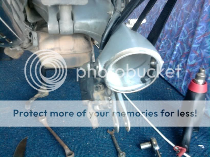
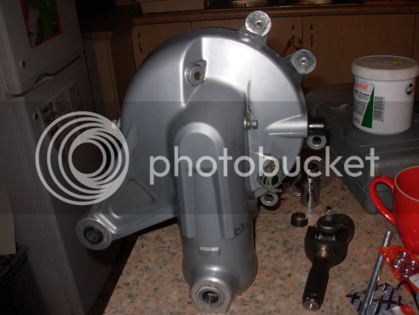
Remove the big loc nut on the left pin, and loosen the right pin a few rotations, just to break the bond, but not remove it. Hold the FD in place and remove both pins (be careful not to let it fall out).
FD removed

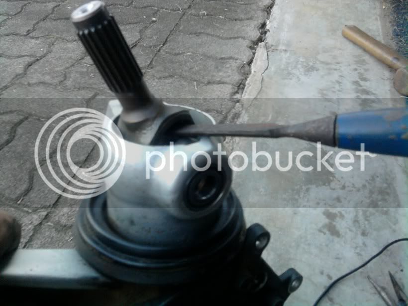
Now pop out the universal. The photo does not show any protective layer between my ultra modern high tech engineering tool, but that was just for the photo. Put something in there so the housing will not be damaged.
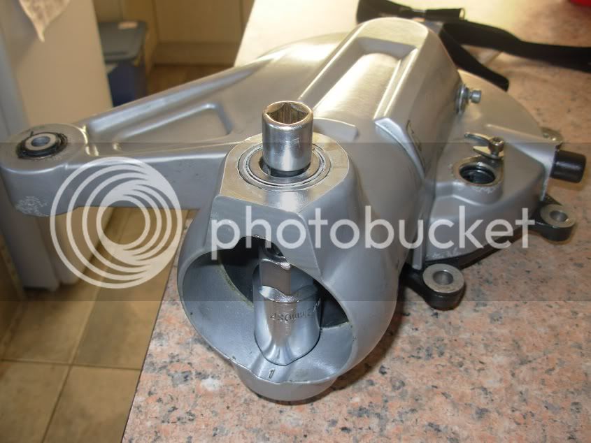
Now to remove the bearings. With a socket extension and some snug fitting sockets (in this case a spark plug socket, for car plugs fit well), gently tap out the old bearing
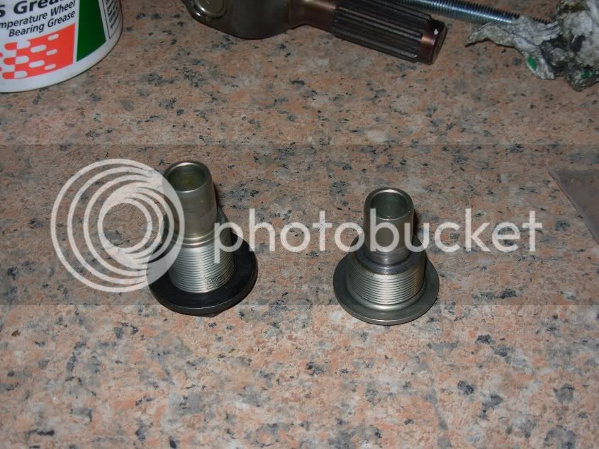
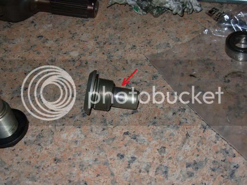
Unfortunately, this was where the spanner fell into the pie and the next problem was encountered. The RH pivot pin was quite badly worn. So I decided to order two new pivot pins, seeing that I am busy in there already. After receiving the new pin, I measured both. The old pin measured 16.88mm, and the new pin 16.99. This was enough to create quite a bit of movement, especially on a seat of only 10mm.
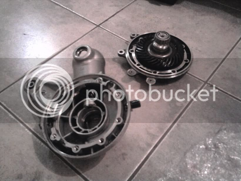
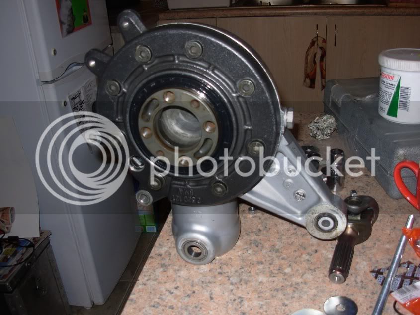
About 7000km ago I replaced my crown gear output bearing, and seeing as I needed to replace the seal as well, I decided to open her up and inspect my previous work. I’m happy to report that no damage is visible :thumleft:
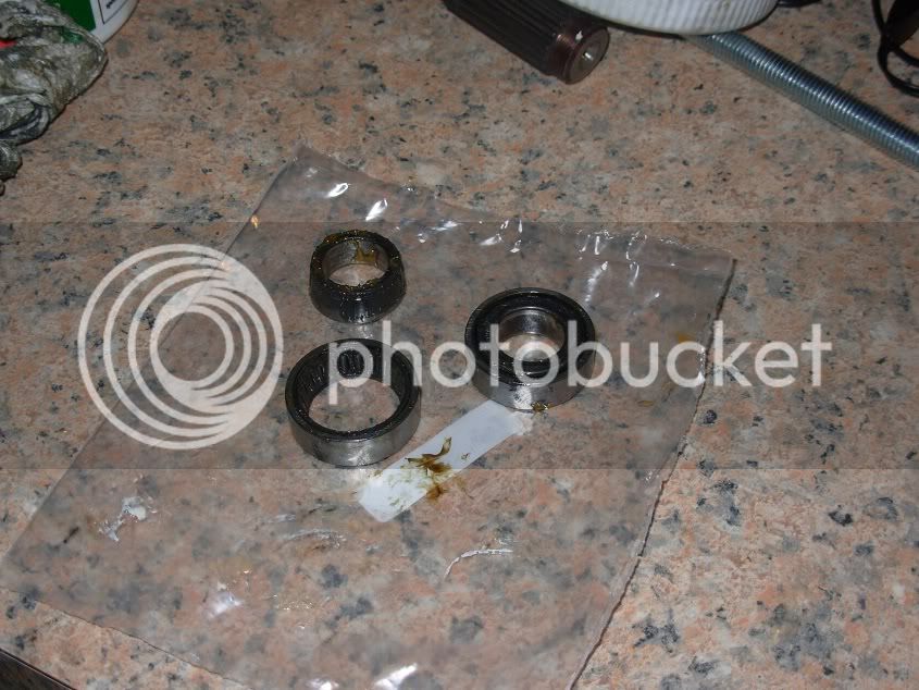
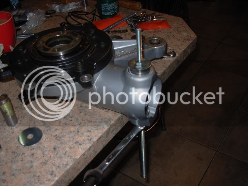
So after cleaning everything, it was time for installing the new bearings. I did this (as seen from quite a few other threads), by using a piece of threaded rod, some washers, sockets and the old bearing races to press the new bearings into place. I also heated the area a bit with a heat gun.
This wasn’t as easy as I thought it would be, however, all was well in the end.
Next step was to pop the Universal joint back into place and put some grease on there
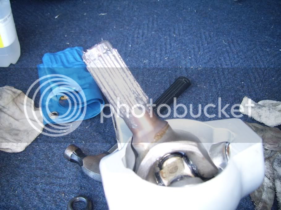
The universals needs to be phased, so after shining a light into the swing arm to determine the position of the front UJ, I turned the front so it is vertical, and the rear on the same “linkage” to be horizontal. Then marked on both splines to ensure they will be inserted correctly
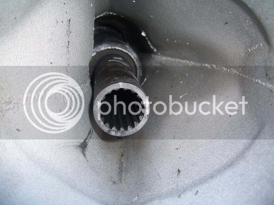
Then slide the splines back into place. The RH pivot pin is inseted first, but not completely. Then the left pin is inserted to hold the FD in place. Next the RH pin is torque, then the LH pin is torque to required (8N.m). Then the Locknut is torque into place. Remember to put the boot on though before the FD is inserted, as this is obviously what I forgot to do.
Play in my rear drive became increasingly pronounced, so after my last ride to the mountains of Pedi, and I realized the bike would not start due to a broken wire in my ignition, I decided it was time for some proper TLC.
On the agenda:
1) Renew ignition harness
2) Replace Paralever Bearings
3) Replace leaking FD output oil seal
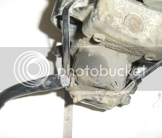
There’s the li’l bugger that caused me such head-ache.
While removing the fork bridge, I noted that the main screw gave quite a lot of resistance all the way while loosening it. The reason: I bought this bike just over a year ago, it was quite apparent that some poor Vespa owner out there is missing a screen. But in order to make this screen fit, the guys who worked on this “pooratech project” removed the main screw and pressed it out of the fork bridge. They then proceeded to clamp the screw in a vice...on the thread (marks are clearly visible) to drill a hole into the screw, skew I might add, and thread it, so they can insert a rather lengthy threaded rod which holds the screen with some contraption they stole from a 5000BC catapult. Anyway, the result is a completely stuffed up thread. I haven’t gone to fix this yet, but going to find out if any-body here can insert some time-serts for me.
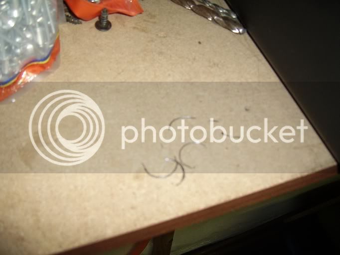
These are pieces of the broken thread that came out while removing the bolt
Fixed the ignition harness with some fresh wire, and installed everything (as is for now), and she roared into life first time.
Then time for the bearings.
Removed the rear wheel and heated the material around the paralever pins with a heat gun to break the loctite bond.
Remove the big loc nut on the left pin, and loosen the right pin a few rotations, just to break the bond, but not remove it. Hold the FD in place and remove both pins (be careful not to let it fall out).
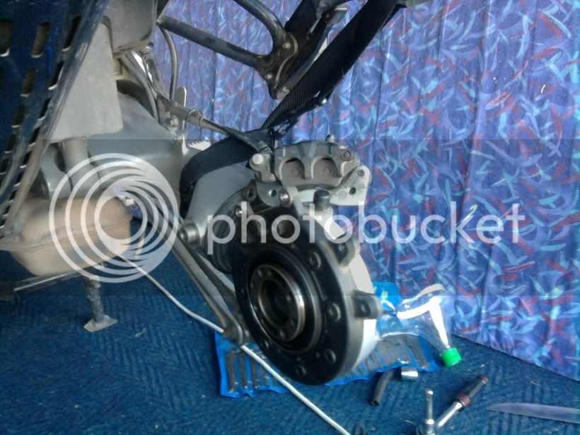
FD removed
Now pop out the universal. The photo does not show any protective layer between my ultra modern high tech engineering tool, but that was just for the photo. Put something in there so the housing will not be damaged.
Now to remove the bearings. With a socket extension and some snug fitting sockets (in this case a spark plug socket, for car plugs fit well), gently tap out the old bearing
Unfortunately, this was where the spanner fell into the pie and the next problem was encountered. The RH pivot pin was quite badly worn. So I decided to order two new pivot pins, seeing that I am busy in there already. After receiving the new pin, I measured both. The old pin measured 16.88mm, and the new pin 16.99. This was enough to create quite a bit of movement, especially on a seat of only 10mm.
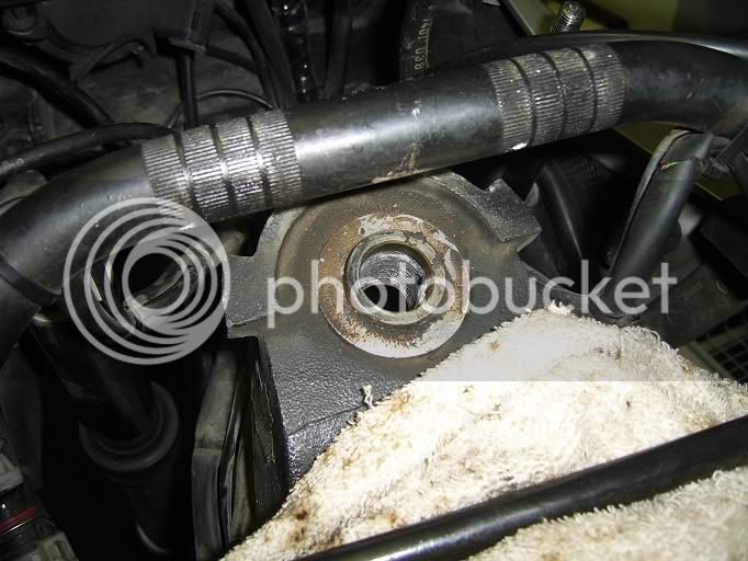
About 7000km ago I replaced my crown gear output bearing, and seeing as I needed to replace the seal as well, I decided to open her up and inspect my previous work. I’m happy to report that no damage is visible :thumleft:
So after cleaning everything, it was time for installing the new bearings. I did this (as seen from quite a few other threads), by using a piece of threaded rod, some washers, sockets and the old bearing races to press the new bearings into place. I also heated the area a bit with a heat gun.
This wasn’t as easy as I thought it would be, however, all was well in the end.
Next step was to pop the Universal joint back into place and put some grease on there
The universals needs to be phased, so after shining a light into the swing arm to determine the position of the front UJ, I turned the front so it is vertical, and the rear on the same “linkage” to be horizontal. Then marked on both splines to ensure they will be inserted correctly
Then slide the splines back into place. The RH pivot pin is inseted first, but not completely. Then the left pin is inserted to hold the FD in place. Next the RH pin is torque, then the LH pin is torque to required (8N.m). Then the Locknut is torque into place. Remember to put the boot on though before the FD is inserted, as this is obviously what I forgot to do.